Practical engineering guides covering valve selection, standards, materials, failure analysis, maintenance, and industry applications.
Core Modules
Eight structured knowledge modules covering the complete lifecycle of industrial valve engineering—from selection through maintenance.

Selecting the correct valve for a given service requires evaluation of pressure class, temperature range, fluid compatibility, flow requirements, and end connection standards. This module covers the complete selection process from service definition through final specification.
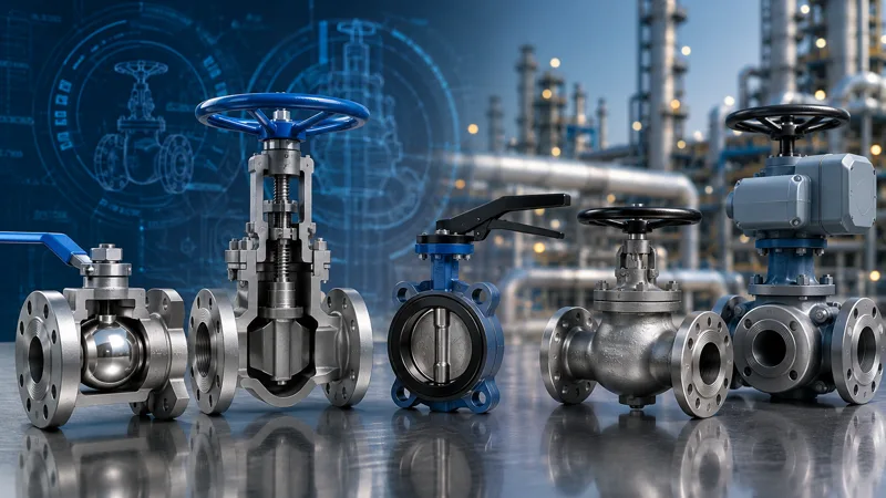
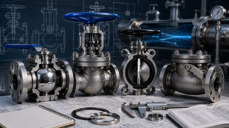
Industrial valves are classified by closure element design, which determines flow characteristic, pressure drop, and suitable service conditions. Understanding each type is essential for correct application and specification.
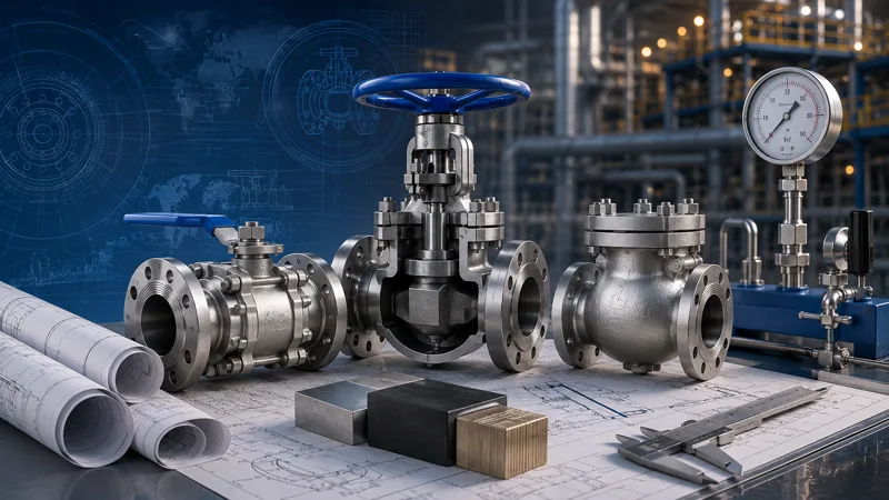
API, ASME, and ISO standards define dimensional, material, testing, and performance requirements for industrial valves. Compliance with applicable standards is mandatory for pipeline, process, and pressure vessel service.
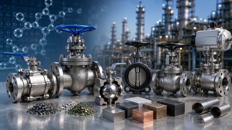
Material selection determines corrosion resistance, mechanical strength, and suitability for process fluid and temperature conditions. Correct material specification prevents premature failure and ensures compliance with applicable pressure equipment directives.
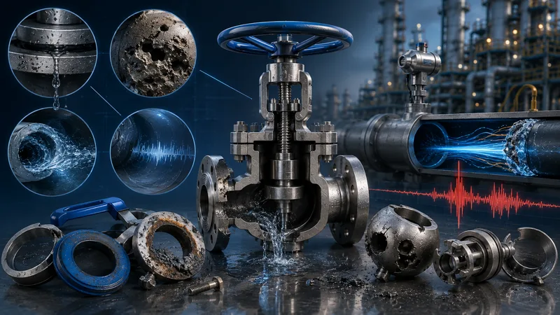
Understanding the root causes of valve failure — including leakage, cavitation, erosion, and water hammer — is essential for preventing unplanned downtime and extending service life in high-pressure and critical process systems.
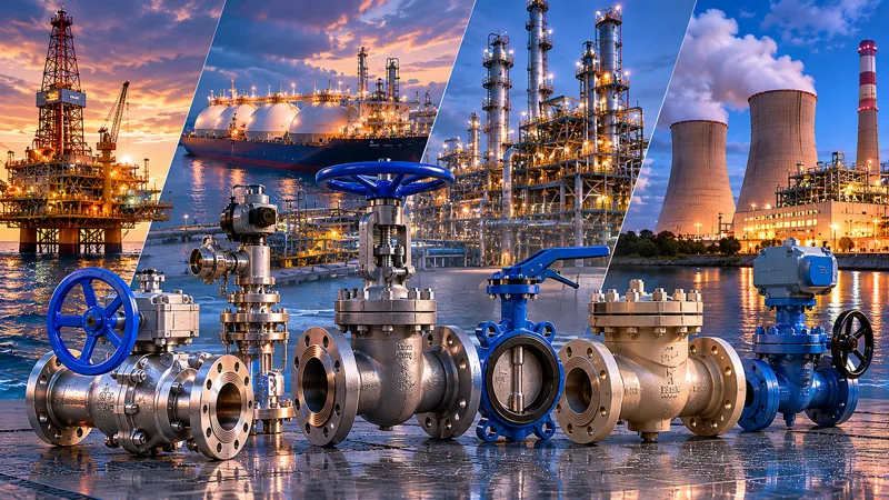
Valve specifications vary significantly across industries. Oil and gas, LNG, power generation, and chemical processing each impose distinct requirements for pressure class, material, end connection, and safety certification that must be addressed during valve selection.
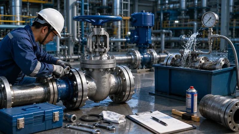
Proper installation, hydrostatic testing, and preventive maintenance procedures are essential for long-term valve performance and compliance with applicable inspection and integrity management requirements.
Consistent use of standardized engineering terminology is essential for accurate valve specification, procurement, and compliance documentation. This module defines the core technical terms used throughout valve datasheets, standards, and engineering specifications.